In the Beginning
By Burt Weiner, K6OQK
There seems to be a lot of stories running around about me having been the chief engineer at KPFK. I never was their chief nor did I ever work for them in any capacity other than having done a few board operating shifts for them as a volunteer back in the mid 50’s while in high school. That was it. That was my only connection to them.
So, where did these stories come from? There have been several people that are said to be the “Official Historians” of the WA6TDD repeater. The problem with these “historians” and the beginning of the repeater is that none of them were there at the time. The repeater moved to the KPFK transmitter building in late 1962. Probably the first person, other than myself to know the real history of the repeater would be Bob Thornburg, WB6JPI, but Bob didn’t arrive on the WA6TDD repeater until sometime in 1965. Other “historians” showed up several years later. From reading the stories attributed to these “historians” I can only say that a lot of assumptions and embellishments were made resulting in a lot of pure fiction about the repeater’s early days.
So, just how did the repeater really come about being in the KPFK building on Mt. Wilson.
My intense interest and desire for building a repeater came after meeting Art Gentry, W6MEP* and seeing his K6MYK repeater located on Mt. Lee above the Hollywood sign. Remote control and automatic systems had always fascinated me, so part of this adventure would be to obtain remote control authorization for K6OQK. Since the application would require schematics and block diagrams, I arranged for the FCC application to become my senior high school drafting class project. The FCC granted the application and simultaneously issued a Second Station call of WA6TDD. That license was assigned to the home of my high school home room and drafting teacher, located near the top of Mulholland and Beverly Glenn.
The first version of the repeater was fairly primitive at best - But it worked!
An acquaintance of mine had become a volunteer board operator at KPFK and one afternoon asked if I wanted to go visit "the station” and see their new studios? I thought that would be fun, so off we went. While we were there I was introduced to Bill Acord who was KPFK’s chief engineer. Bill and I became friends and one day, maybe two or three months later, I privately asked him about the possibility of putting the repeater in their building on Mt. Wilson. I really expected to be politely turned down, but to my amazement, he was very receptive of the idea. Bill told me he'd have to get permission from management and would let me know. KPFK management said they'd have to check with their FCC Council to find out whether or not this would be legal or even advisable. This was back in 1961 and this part of the process was long and painful for me. Here, this wonderful carrot had been dangled in front of me and was just close enough that I could see and smell it yet it was far enough that I couldn't grab it!
Periodically I’d call Bill to ask if he’d heard anything. I was really afraid of becoming a pest and afraid he’d ask me to stop annoying him. Instead, Bill was always patient and very cordial towards me. After almost a year of waiting I became so frustrated that I finally called Bill with the intent of saying something like, let's forget it because I know it's not going to happen.
Before I could get a word out Bill told me that he had just heard from the station's management and their FCC attorneys and that it was approved. He said there were some stipulations that we'd have to work with: One, I could not have access to the building unless I was accompanied by a station engineer or until such time as I obtained a First Class Radio Telephone license. Second, I would need to get a Forestry Permit before installing the repeater in the building. A few months later I had my First Class Radio Telephone License.
An agreement was drawn up and blessed by the station's management and attorneys. Several years later, and many managers later, the agreement was modified by Pacifica’s Corporate office, which gave me more room and more freedom for the repeater. The agreement states, "...in exchange for a valuable consideration..." The consideration was that I'd help with transmitter issues as needed. That agreement is still in effect and I still help when I can in spite of being well beyond my “Sell Before” date.
Bill Acord helped me get the Forestry Permit, and Skip Benediktson, the local Forest Ranger in charge of the Mt. Wilson Electronics Area helped to get the permit application through all the red tape. Part of the Forestry Permit application required an “On-Air Test” for any interference. I had to notify all Mt. Wilson Forestry Permit holders 30-days in advance of the test by Certified Mail with a Return Receipt requested, and they in turn had to notify me of any interference. The test began on December 14, 1962 and went through January 2nd, 1963. There was one problem which was resolved by moving the repeater transmitter from the original application frequency of 146.50 MHz to 146.40 MHz. There were no other problems and on January 2nd, 1963 the repeater had a full blessing from Forestry and was allowed to begin regular operation.
WA6TDD originally received on 145.424 MHz. The reason for the strange input frequency is simple: Steve Jensen, W6RHM had a Stoddard NM-30 Interference Meter (a fancy Instrumentation receiver) and a Heathkit Pawnee that covered 2-Meters. Using both of these, Steve and I tuned around until we found a spot that was consistently low in noise and intermodulation products from other equipment on Mt. Wilson. Once we found a spot we measured the frequency with a Gertsch FM-7, rounded it off to the nearest Kilocycle (kHz) and proclaimed it the input. Several years later a FM input was added at 145.195 MHz.
By the fall of 1972 the 2-Meter band had become loaded with repeaters that had popped up on random frequencies. Out of necessity there was this really big Frequency Coordination meeting held and all of the 2-Meter repeaters in Southern California would have to fall into the new plan. No one was allowed to leave until all the repeaters had a frequency pair that fell within the plan. I couldn't (wouldn't) move the output because of the Forestry Permit issues, but I finally agreed to move the input - But, I needed both an AM input and a FM input. After a lot of lively discussion, and I suppose because everyone was getting hungry and wanted to go home, I was coordinated on 147.42 for the AM input and 147.435 for the FM input with 146.40 remaining as the output for both. The transmitter was 100% AM modulated, and simultaneously about 3 kHz FM deviation. The AM input went away a few years later leaving only the FM input on 147.435 MHz. That's how the odd input and output frequencies came about.
We had a lot of family events such as Operation Santa Clause, T-Hunts and of course, regular breakfasts, lunches, dinners, picnics, and the infamous Craig Robbins’ (WA6RAT / WB6FVC) Chicken Fests – actually any opportunity to eat. While we had a lot of fun and probably got into our fair share of mischief, everyone was pretty respectful of each other.
We rarely had the problems that the .435 repeater currently has the reputation for. However, as with any large group, there were a few jerks. (Personally, I'd rather have people think well of me.)
Please take a look at:
https://www.youtube.com/watch?v=Ik6LUs60S9c
And then:
https://www.youtube.com/watch?v=_pjJfz8RHsg
The two video clips were made without any preparation. I didn't know about it until Bob Jensen (W6VGQ) (SK) came over to our home, stuffed a mic in my face and said, "Burt, Tell us about the repeater."
Please see the sidebar in Bill Pasternak's article telling how I met Art & Millie Gentry. It can be found at: http://www.arrl.org/files/file/Technology/tis/info/pdf/pasterna.pdf.
A lot of the original WA6TDD / WR6ABE repeater is still in my garage.
Burt, K6OQK
biwa@att.net
www.biwa.cc
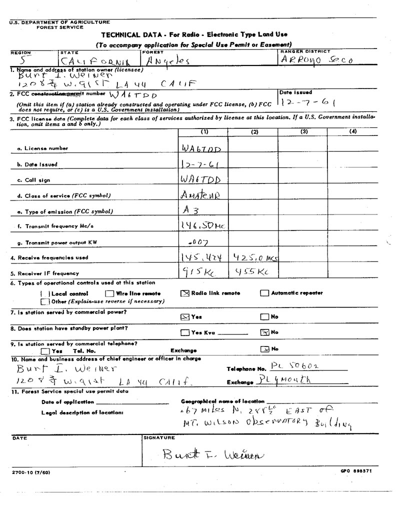
WA6TDD Forestry Application - Technical Data
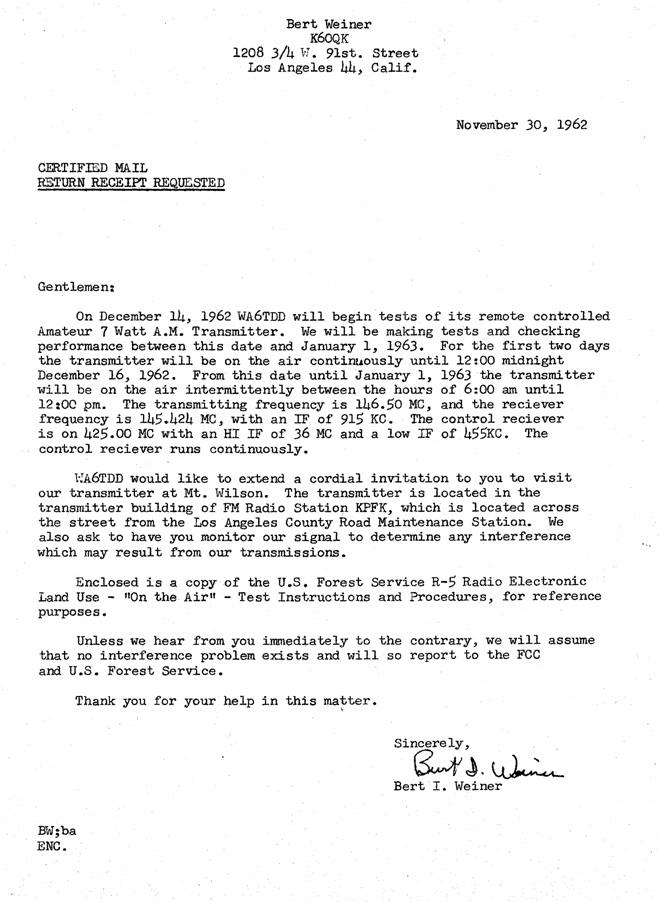
WA6TDD On-Air Test Notification Letter
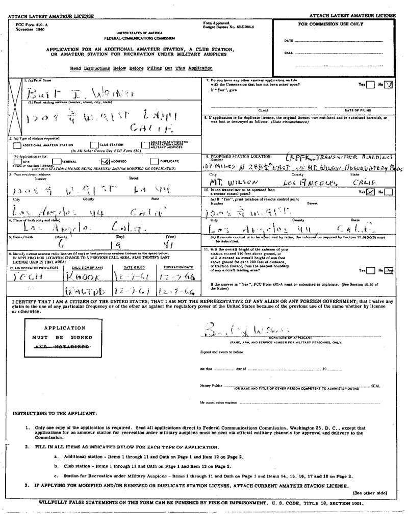
Application to move WA6TDD to Mt. Wilson - Page 1 0f 2
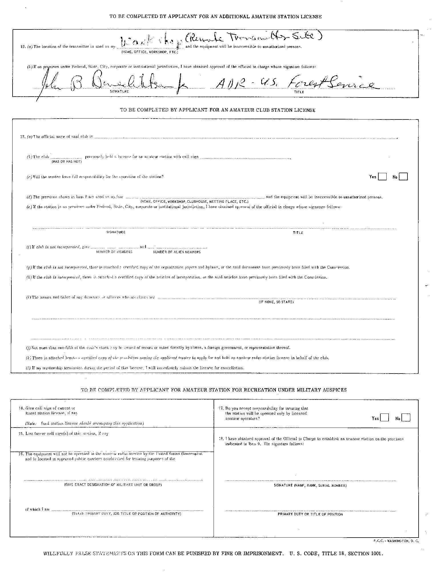
Application to move WA6TDD to Mt. Wilson - Page 2 0f 2
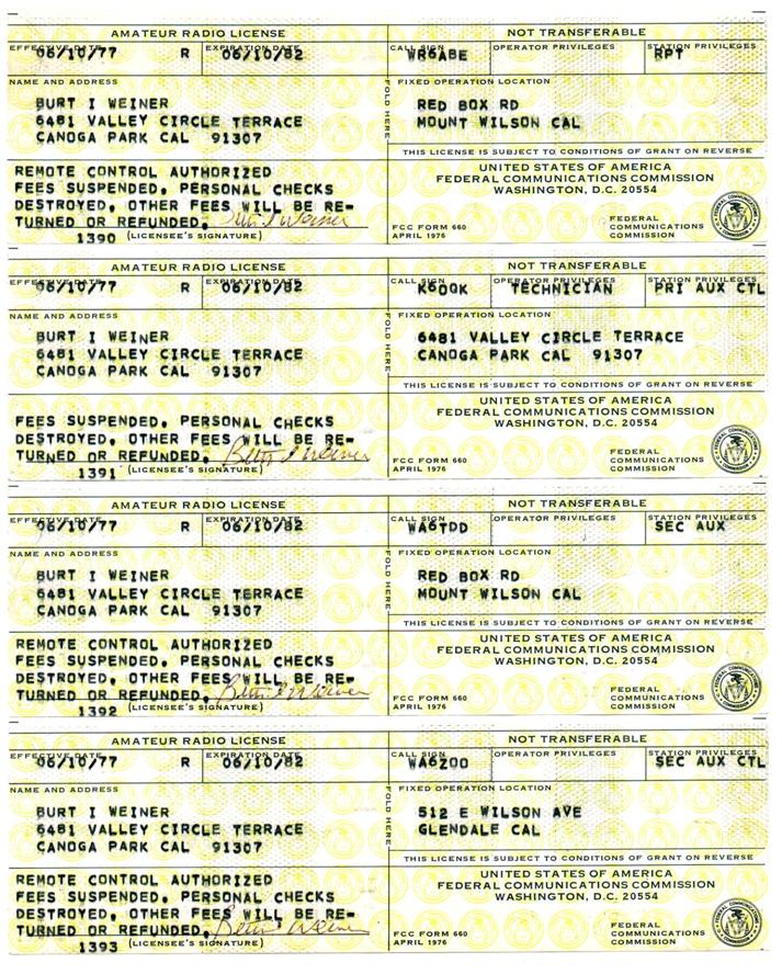
WA6TDD / WR6ABE Radio Control Point Licenses
WR6ABE Radio & Phone Line Control Point Authorization
In Deep Appreciation…
Before I tell you about the repeater I want to take a moment to give thanks and credit to a lot of people who made it all possible.
The user base for the repeater consisted of many people with diverse and extraordinary technical backgrounds. They were always there and willing to share their knowledge at a time when it was needed.
There were many people along the way that helped by not only donating equipment, time, money and knowledge, but also by making sure that I ate and stayed healthy.
Art (W6MEP) and Millie (K6JJN) Gentry were longtime friends who had a lot of patience with this annoying kid. Art was a wonderful mentor as well as a close personal friend and advisor about more than just radio. Their passing has been a great personal loss for me.
To Bill Acord, KPFK’s chief engineer at the time the repeater moved to Mt. Wilson. Bill really is the person that made it happen. To Don Wilson (K6DSW) who later became KPFK’s chief engineer and was very supportive of the repeater. Don helped in accomplishing many of the upgrades including moving the repeater’s antenna to the top of the tower.
And to Dan Saltzman (WB6MVP), a longtime friend who so graciously offered to a put together a web page about the early history of the repeater.
I sincerely thank all of you.
Burt Weiner, K6OQK – biwa@att.net
HOW I DID IT
The WA6TDD repeater grew out of my interest in broadcast engineering. Over the years it evolved from home-brewed and modified military surplus equipment and old two-way radio gear, to used broadcast radio and television station equipment.
The repeater was a versatile system. It was a lot more than just a receiver and transmitter connected together. The more that I could make it do, the more I wanted to add to it. I could turn on a mic inside the rack to hear the repeater’s relays clunking as well as other sounds inside the building, and we certainly did hear some truly thought provoking sounds and squealing. It grew from a single rack to three racks full of stuff and a transmitter that took up just as much floor space, as well as the top of the broadcast station's tower - with the station's blessing.
Duplex mode made it possible to mix in sounds such as the endless tape cartridge of the cricket with certain victim stations. I remember one station that almost tore his house apart looking for the cricket that he heard only on his signal while operating duplex through the repeater. Strange, it was only on when he was on. I remember my Grandmother telling me not to mix in.
Through the control link’s duplex mode we could run multiple ID's from tape cartridges to fit the season. There was also a cart that ran repeater ID's in every language in which we could get them recorded. Kelly Lange of Channel 4 News fame was the "Repeater Lady", although she never knew it until after the fact and then wanted to know, "What’s this about a peter on a mountain???” She had been asked to record an I.D. for something that made no sense to her but graciously did it anyway.
Two people who found a way to take advantage of the capabilities of the repeater were Jim “Woody” Wood (K6BXW) and Bill Butler Sr. (W6BFA). With the help of the many Hams that worked with them so unselfishly they put together “Operation Santa”, not only on the WA6TDD repeater but also the K6MYK repeater. Woody and Bill found a way to make the two repeater's separate and combined coverage and penetration do a good thing to bring a smile to a lot of kids that might otherwise have had a sad and lonely Christmas.
WA6TDD and K6MYK were two totally separate repeaters, but one big family. I know that Art and I shared in the feeling that the intent was for us all to enjoy and learn from each other.
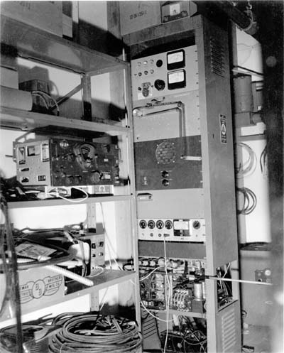
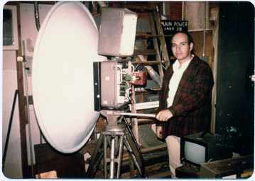
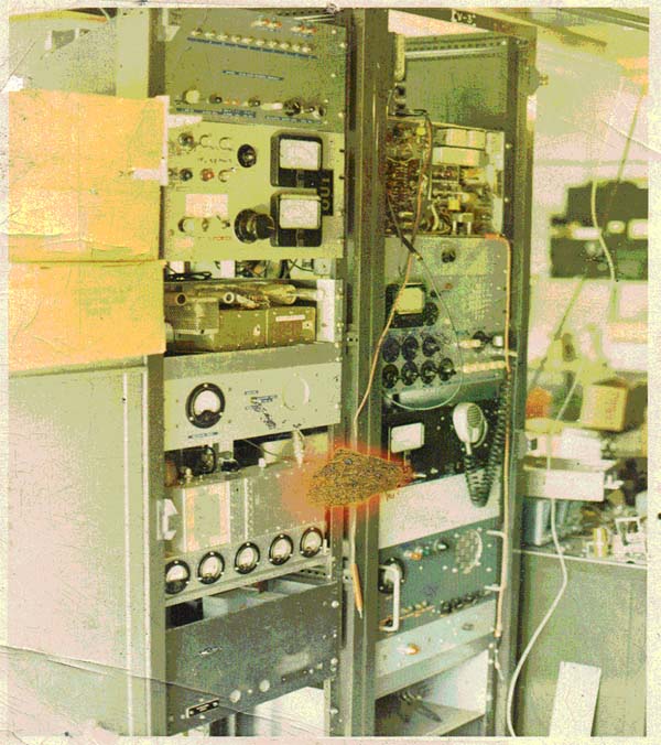
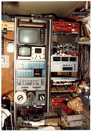
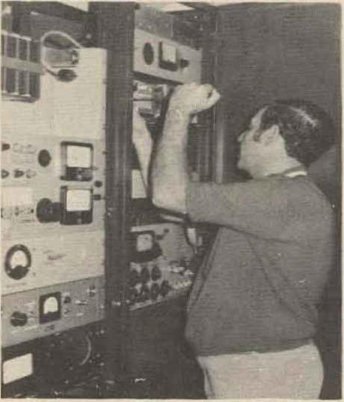
This is it, the original “WA6TDD Mt. Wilson Repeater” as installed in the back corner of the KPFK transmitter building on Mt. Wilson in 1962.
The equipment in the rack starting from the top is: The greatly modified ARC-4 transmitter, the 35 mm Mag-stripe MCW ID loop, a monitor speaker and amplifier, the repeater logic including a Veeder-Root "Beep counter", the audio mixer and early AGC audio processing, the remote control relay interface strip, and the ARC-1 receiver and it's power supply. On the shelf to the left is the BC-348 receiver used as the 2nd I.F. for the ARC-1.
In spite of all this lacking anything closely resembling “state of the art” for the time, as a repeater it worked quite well. Of course, being on Mt. Wilson didn’t hurt.
The ARC-4 was modified for higher fidelity using UTC wideband audio input and modulation transformers and the modulator’s circuitry was copied from a Williamson Ultra High Fidelity Audio Amplifier. The transmitter output was about 9 Watts. The 35 mm Mag-Stripe film used for the ID loop had holes punched in it using a single-hole paper punch. A small piece of silver solder used as a spring contact was the keying lead. The Mag-Stripe rode between that contact and a grounded block of silver from an arc projector carbon clamp that was donated by a Ham/projectionist at a local drive-in theater. The automatic control for the repeater was diode-relay logic with capacitors for timing the transmitter carrier control delays and "Beeps". The audio chassis mixed the beep level, the MCW ID, the local mic, the link receiver, and the 2-Meter receiver levels. The audio AGC was pretty much a copy of Art Gentry's K6MYK repeater audio processor.
The wire-line remote control used a D.C. pair from the phone company. D.C. on the line would cause the repeater to be enabled and come on the air. A short reverse D.C. pulse would cause the audio to transfer to... well, nothing. At that time there wasn't anything for it to transfer to, but it would do it anyway, basically muting the audio. A 10-second loss of D.C. would cause the system to turn off.
The ARC-1 is sitting on its side near the lower left side of the rack. You can see a shorted stub tuner sticking out of its antenna connection to the right past the edge of the rack. This was the only protection the receiver had from the transmitter other than the antenna's approximately 100' of vertical separation. The ARC-1 receiver was pretty broad so I decided to use my trusty BC-348 receiver which had an added TNS (Twin Noise Squelch), as a second I.F. combination squelch and noise limiter. It was tuned to the ARC-1's I.F., somewhere around 9700 KC. This had a most unexpected result.
One evening a monster carrier came on the input of the WA6TDD repeater. To simply say that it was really strong wouldn’t have begun to do it justice. The strongest signals on the input could only make a small heterodyne against it. Everyone was calling everyone on the phone -- “Can you hear it???!!!” No one could hear it, which was strange considering how strong it was into the repeater. After about 30 minutes audio came on and it identified. We were greeted with, “Columbia, The Gem of The Ocean”. It was the Voice of America running a bazillion or so watts on 9705 KC from their Delano, California transmitter and walking through the very poorly shielded I.F. cable between the ARC-1 and the BC-348.
The large EICO VTVM sitting on the shelf and a Heathkit Signal Tracer were the only pieces of test equipment that I owned. Later, Woody, K6BXW donated a set of EICO Audio and RF signal generators to my collection. I still have them.
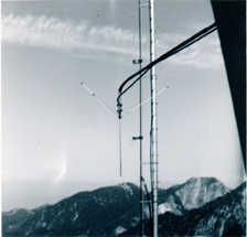
WA6TDD’s first receive antenna was this upside down ground plane at about the 100 foot level on the tower. The reason it was upside down was so the main lobe of the antenna would go down towards the city rather than up over the city. The difference between having it right-side up or upside down was quite noticeable. Having it upside down also made it easier to fill up with water.
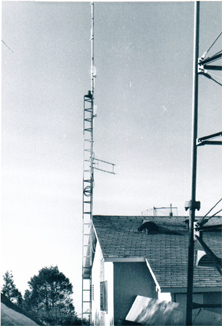
This is the 4 element Cushcraft J-Pole antenna that was originally used for the transmitter. Even though the J-Pole had much higher gain than the ground plane, considering its shorter coax run and higher antenna gain, the ground plane at 100 feet did a better job of hearing because it cleared nearby higher terrain to the east. This picture of the J-Pole was taken several months after the repeater first went on the air and shows the addition of the 420 Mc Skeleton-Slot antenna used for the control link.

A few months later this Cushcraft J-Pole replaced the upside down ground plane antenna used for the receiver. The top was about 85 feet above the ground. After a short time we swung the antenna about another 30 degrees towards the southwest and rotated all of the elements about 10 degrees apart centered towards Long Beach. This improved coverage from Orange County to Santa Barbara quite noticeably. The J-Pole magically survived snow and falling ice for several years. This was also a great lesson in why unjacketed hard line should be avoided at any cost.
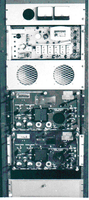
Below are pictures of the WA6TDD AM receiver. This was pretty much a copy of Art, W6MEP's K6MYK AM receiver. Near the upper left you can see the bottom of the 16 kHz Collins Mechanical Filter with the trimmer on one end. It had a DC Amplified AVC system that drove a very low impedance AVC buss. This got rid of a lot of the flutter that had previously been so typical of mobile signals
The Mechanical Filter made the receiver so narrow that crystals in Gonset Communicators and some other rigs would heat up and slowly drift out of the receiver’s passband, turning signals into what sounded like single-sideband and then disappear. Some users took the crystals out of their rigs during receive. Many users would grind their crystals so that they’d be on the edge of the passband and slowly drift towards the center. The repeater receiver’s crystal was in a double oven to keep the passband centered on the input frequency.
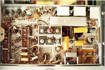
This is looking into the front of The WA6TDD AM Receiver with the cover removed.
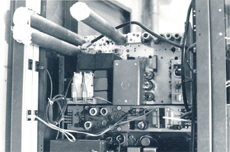
This is the rear view of The WA6TDD AM receiver showing the two input bandpass cavities and the cavity trap on the mixer grid. The two relays are for the squelch control motor located in the box near the center bottom of the receiver. The receiver was originally a Wilcox Electric Aircraft receiver that was stripped down to the bare chassis.
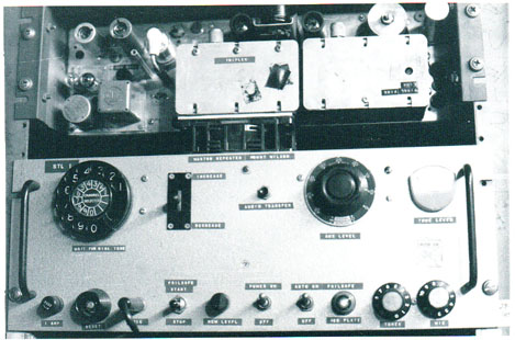
This is the WA6TDD repeater’s first radio remote control system that I built back around 1964. The transmitter is a G.E. Pre-Progress Line 420 MHz transmitter. If you look just to the right of the transmitter’s crystal oven you can see where it was modified for Direct FM. The transmitter ran about 5 Watts out and fed an “8 over 8” Skeleton Slot antenna that looked right into the side of a small mountain between me and Mt. Wilson and only about a block from our home. I was always on the lookout for usable 2C39/7289 tubes for this transmitter.
The FCC required the control system to be fail-safe. To meet this requirement the system was set up so that if the control link receiver at Mt. Wilson lost the control link signal the repeater transmitter would shut off. The fail-safe switch turned the link transmitter on or off.
Just below the transmitter is the control unit. The system used 4 super-sonic tones that controlled the Step/Reset, On and Off (Raise and Lower), and Audio Transfer. The dial controlled a 26-position stepper switch at Mt. Wilson and the reset button just below the phone dial would send the stepper to the home or zero position by sending a one-second long step pulse.
Each position of the stepper had a raise and lower function associated with it that was controlled by the lever switch just to the right of the dial. By dialing a particular position you could either turn a function on or off, or run a motor one way or the other to adjust the receiver’s squelch or the transmitter’s modulation level, or whatever else might need turning.
The repeater's transmitter On/Off function, Stepper position #2, raise and lower controlled a 10-position Minor Switch – sort of a remote controlled 2 pole 10 position switch. The repeater had 4 modes of operation and each time you sent a raise pulse to stepper position # 2, it would send the Minor Switch up one position selecting one of the modes. Position # 1 was Automatic with delayed drop off, which was the normal operating mode; Position # 2 was Direct Key which caused the transmitter to go on and off following the incoming signal without the delayed drop off; Position # 3 was Continuous Carrier where the repeater's carrier was always on; Position # 4 keyed the transmitter only by the push to talk on the control link – as if it were a remote base. Lower would send the Minor Switch to its zero or off position turning the transmitter off.
The audio transfer button operated an Automatic Electric OCS Binary switch in the repeater's audio deck. This was a gazillion pole two position switch that would toggle from one position to the other with each command pulse. Stepper position # 3 raise on the remote control operated the transfer function the same as the audio transfer button. Stepper position # 3 lower operated a second OCS Binary switch and toggled "Duplex" mode on and off. Duplex mode mixed the control link audio in with the 2-Meter receiver instead of hard switching between the two. This allowed the control operator to work duplex through the repeater.
I wanted to be able to control the repeater without always having to go into the radio room, so I modified an old TV supersonic remote control box to operate the repeater’s control system from around our small home. The channel up and down controlled the stepper switch position and the volume up and down controlled the raise and lower functions. The TV remote control receiver’s relays simply paralleled the front panel controls in the repeater’s remote control system at home.
One day a group of Hams from another repeater asked how I controlled the WA6TDD repeater. I invited them over so I could show them. When they arrived I took the TV remote control, opened the front door and pointed it towards Mt. Wilson and proceeded to control the repeater for them. Before this, I’d heard about, but I’d never actually seen anyone’s eyes bug out of their head. To say they were amazed would be a gross understatement. After a few minutes I told them the truth and showed them the actual controller. I was glad to see that they also had a sense of humor. I suspect they are still laughing and shaking their heads.
I wanted something more reliable than the supersonic TV controller. I finally built a small, portable control box that was on a 50 foot cable connected to the remote control system. It had a speaker, mic jack, telephone dial and switches that duplicated all of the basic functions of the main controller. I could drag it around and control the repeater from anywhere in the house. Even from in there. I still have the control unit safely tucked away.
Sometime around 1979 I acquired a RCA TVM-1, a 1-Watt 7 GHz broadcast television microwave system. Since the microwave transmitter and receiver both had cavity type frequency meters we were able to measure the operating frequencies. With the help of Al Hitterdal (W6ILL), Klystrons were found that put the transmitter in the 5650-5925 MHz Amateur Band, but getting the receiver down into the Ham Band was a problem. We couldn’t find a Klystron that would work as the receiver's L.O. for the Ham Band. We discovered that a Klystron intended for the transmitter would work on the needed frequency when installed in the receiver. Apparently the Klystron would jump mode with the lower voltage of the receiver and we were able to get the correct L.O. injection of Fc+130 (MHz). This became the repeater’s control link or STL, which in this case stood for "Shack-Transmitter-Link.
There was a problem with the microwave’s I.F. being 20-Plus MHz wide and centered on 130 MHz. The microwave receiver was being interfered with by the 146.40 MHz output of the repeater. This was quickly resolved by a “spontaneously crafted” 146.40 MHz series resonant trap to ground at the output BNC connector of the microwave receiver's down-converter. This filter totally removed the interference to the microwave receiver.
Another interesting problem arose when we discovered that if the microwave receiver lost signal, such as during a deep fade or power interruption at home, the AFC would drive the Klystron around searching for signal, and eventually to the point where the Klystron dropped out of oscillation and the receiver would quit. In the beginning this meant a trip to Mt. Wilson to turn the AFC off and then back on. I built a carrier operated relay that sensed when the carrier dropped below a pre-determined level and would disable the AFC keeping the receiver at its' nominal center. This completely resolved the problem, which was a good thing because it was a long drive from Woodland Hills to Mt. Wilson.
Having the wide baseband bandwidth opened up new possibilities. I was now able to add two 15 kHz bandwidth audio sub-channels, one at 6.2 MHz and another at 6.8 MHz as well as having 5-plus MHz of space for video. On the 6.8 MHz subcarrier I added a 185 kHz subcarrier that contained the primary control for the repeater.
The remote control system graduated from the original homebrewed system to a Moseley PBR-15 and a short time later to a Moseley PBR-30. The return sub-audible metering ran from 20-30 Hz and was applied to the buffer stage cathode of the main and auxiliary transmitters which caused the repeater’s transmitters to deviate about 50 Hz with the telemetering. I had to put a 50 Hz High Pass filter at the audio input to the transmitters to keep the repeater’s audio from interfering with the low frequency metering signal. A high gain amplifier and low-pass filter was installed in the G.E. ER-1 monitor receiver at home to drive the PBR-30’s metering input. I now had full telemetering. In order to calibrate the metering system I had a small surveillance type TV camera looking at the receive end meter. I was able to see the meter on a TV monitor at the mountain and calibrate the metering system.
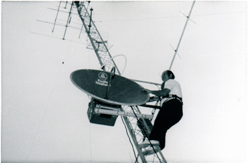
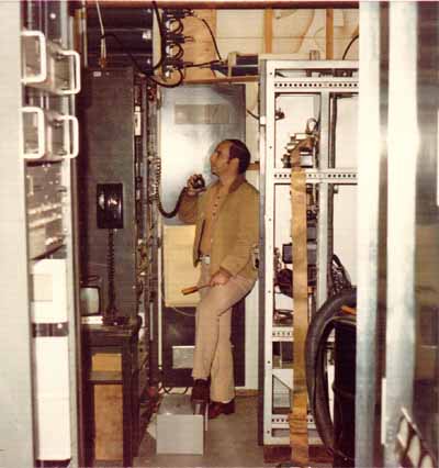
The microwave signal was so strong at the mountain that the 0-500 Signal meter on the receiver was almost always pinned. In the picture below you can see the Klystron and down converter mounted to the back of the dish. Fletch (W6DEO) built a platform located just inside and above the door of the building. This became the home of the dish as well as a storage place for many years.
Burt (K6OQK) looking like a deer in the headlights. This is the dish looking through the west wall of the KPFK transmitter building. The signal strength meter was pinned.
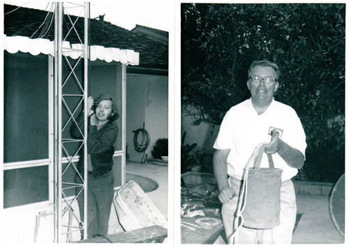
Bill Pasternak (WA6ITF) left, and Al Hitterdal (W6ILL) helped in putting the microwave transmitter head and the 4-foot dish on the tower at our home in West Van Nuys.
This is K6OQK on the tower at home making initial adjustments to the 4' STL transmit dish. The dish was just high enough to comfortably clear trees about two blocks away. The path length to Mt. Wilson was 26 miles.
Alignment of the transmit dish was easy to accomplish. Since the remote control system was able to bring back the microwave receiver’s signal strength reading it was a simple matter to take that reading out of the remote control and feed it up a spare pair in the transmitter control cable to an unused position of the meter switch in the back of the transmitter head. This made it possible to see the receive signal strength at Mt. Wilson while aiming the transmit antenna without the need for a middleman to relay signal strength readings.
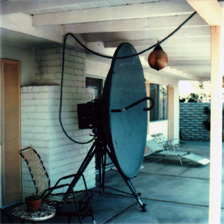
After a few years we moved to a high location at the west end of Woodland Hills. This was a great radio location! In order to maintain the repeater’s control system during our settling in, I set up a temporary microwave transmitter on a tripod in our patio.
From here the 34 mile long microwave shot to Mt. Wilson was an optical path from the ground. Coincidentally, the difference in path azimuth between our previous home and our new home was only 0.4 degree and the difference in elevation angle was less than 0.3 degree. The received signal at Mt. Wilson was so strong and reliable from this location that it even worked with the feed removed from the receive dish at Mt. Wilson. The transmitter output was just a tad over 1 Watt and the 6-foot dish had a gain of 40 dB at this frequency. Microwave is really neat stuff!
Burt, K6OQK
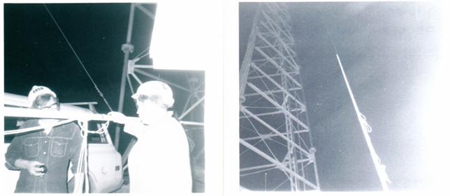
The Great Erection
The biggest improvement to the repeater's coverage came in 1975 when we put a Phelps Dodge Storm Master Antenna on the top of the tower and fed it with 225 feet of 1-5/8" Heliax. The Storm Master, a heavy duty version of their Super Station Master series of antennas, had a gain of 5.2 dB and was custom built by Phelps Dodge to have 1.5 degrees of electrical tilt and mounted to have another 1.5 degrees of mechanical tilt towards Long Beach. The antenna was 20 feet long and the base of the antenna was 178 feet above ground level. This got us well above nearby terrain that until now had partially shielded us to the east. We also became the station's lightning rod.
In order to do this we needed an analysis of the tower by a structural engineer licensed in Los Angeles. Fortunately I had the original “as built” schematic and calculations for the tower and foundation from Dresser-IDECO. As luck would have it, Jerry Walker (WA6LLX) was a structural engineer with the necessary credentials and was on the repeater. The tower was blessed to carry the additional loading with our antenna on top of the tower in accordance with Los Angeles County requirements.
We were not able to do the work with the FM broadcast station on the air at full power, so arrangements were made to lower the power to 1000 Watts between 12 Midnight and 6 AM.
Around 6 PM people started showing up with campers and motor homes so that all in attendance, especially the tower riggers, would have some of the comforts of home including food - a lot of food! There was great camaraderie working for long hours up on top of the tower with a crew full of beans, steaks, hot dogs, hamburgers, and as Bob Thornburg (WB6JPI) who was on the ground at the bottom of the tower will attest, beverages.
Picture # 1 was taken about a week after the antenna went up while adding a few final embellishments during the daytime. It shows the crew - Burt (K6OQK), Orlo (K6SUJ), and Mike (WB6RHW). We were able to do this during the daytime because we also replaced an element on the FM broadcast antenna. You can see the repeater’s 1-5/8" transmission line going up the right leg of the tower.
Picture # 2 shows the antenna support that was made to interface the top splice-plate of the tower to the antenna. The base plate is 3/4" thick with a 3" support pipe about 4 feet long. The arc welding was certified and the entire mount was Hot-Dipped Galvanized after fabrication. You can see the top end of the 1-5/8" line and the pig-tail lead. Due to the high RF, it was necessary to bond the top of the Heliax and the pigtail at several locations to the tower to keep it from going up in flames. Quite often we'd be asked about the repeater’s power. I remember more than once stating that it was running close to 110,000 Watts. This was true. It was close enough to 110,000 Watts to burn stuff up. However, the repeater itself ran about 100 Watts ERP.
About a year later we had a major storm and the antenna iced up pretty bad. This was discussed with Phelps Dodge and they suggested we paint the antenna with black epoxy paint. We did that and never had another incident of the antenna icing up. As far as we could determine there was no degradation in the antenna's performance by painting it.
Bob, WB6JPI & Russ WA6DUC. The antenna on its way up the tower.
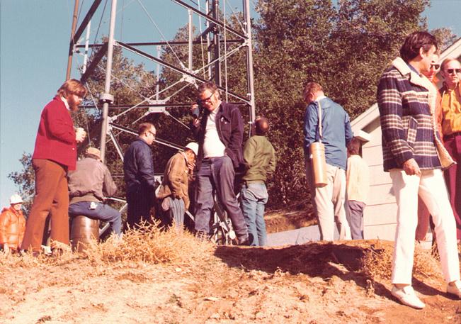
?, WA6OPO, ?, WB6QFR, WA6DUC, WB6JPI, WB6MVP, W6ILL, ?, HC2RP, ?, ?
Some of the folks who showed up to admire the aftermath of the Great Erection.
If anyone knows who the question marks are please send it to WB6MVP's email ;ed
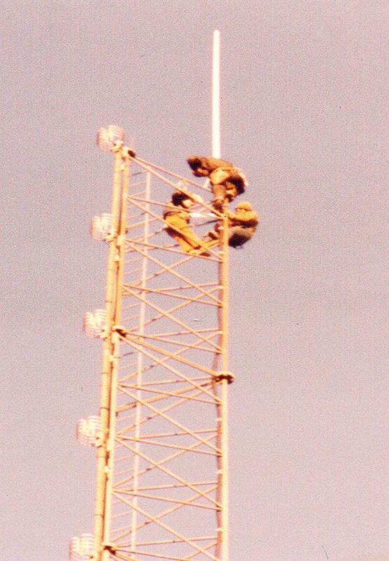
Picture # 1
Burt (K6OQK), Mike (WB6RHW) and Orlo (K6SUJ) putting final embellishments on the WA6TDD / WR6ABE Repeater’s Storm Master Antenna in its new home.
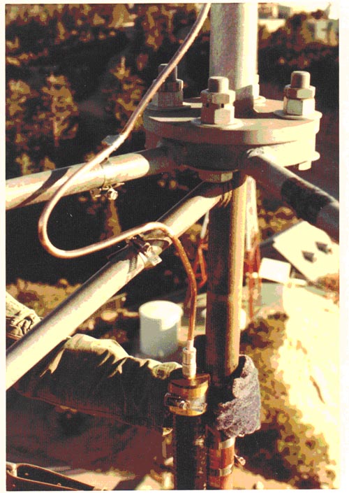
Picture # 2
The WA6TDD / WR6ABE Antenna Base at the top of the tower on Mt. Wilson.
The Circular Antenna and 1200 Watts
About 1980 The Jampro Antenna Company in Sacramento built a single bay, center mounted Circularly Polarized antenna specifically for the WA6TDD / WR6ABE repeater. It temporarily replaced the Storm Master vertical-only antenna and was located about 8 feet above the top of the tower. This was a great transmit antenna, even at low power, but did not work out well for receiving due to its low gain, about -3 dB. With the single bay circular antenna the ERP of the system went from 100 Watts to about 13 Watts. But even with this lower ERP there was a remarkable improvement in the coverage and penetration of the repeater’s signal. For example – I used to work in a building in the Wilshire area that had 5 floors of underground parking. With the Storm Master I would completely lose the signal about 20 feet after driving into the parking entrance. With the circular antenna and the 13 Watts ERP I could carry it solid to the end of the 1st level and hear it intermittently down to the 5th level. Those who regularly drove the Santa Ana Canyon and the Sepulveda Pass, as well as other canyon passes commented on how consistent and reliable the signal was compared to the Storm Master. People listening to the repeater on Radio Shack Patrolman radios said that they no longer had to keep the radios near a window, the repeater could be heard reliably anywhere in their home.
Some people bitterly complained that the repeater was no longer “20 over 9”, it was now only “10 over 9”. They couldn’t grasp the idea that reliability and penetration over wide coverage was more important than simple signal strength. Had the circular antenna worked as well for receive as it did for transmit we could’ve simply increased the transmitter power. Unfortunately, the antenna aperture was physically very small and with its -3 dB gain, it just didn’t work for receiving. Thought was given to mounting both the Station Master and the Jampro at the top of the tower, but this presented both pattern and structural issues that made such an endeavor undesirable. A multiple bay circular antenna was also considered but this presented structural issues at the time so we finally went back to the Station Master antenna.
Just for the fun of it, and for a short time, we fed the Jampro antenna with a RCA BTF-1C FM Broadcast transmitter. The RCA transmitter was easy to modify for 2-Meters. The exciter was a Marti RPT-40 RPU transmitter that easily tuned to 2-Meters. The Marti drove the parallel 4-125-A tubes in the RCA’s driver stage. The final was a grounded-grid 5762 Triode. It delivered 1200 Watts into the 1-5/8 inch transmission line to the antenna giving an ERP of about 500 Watts. Due to the high power we couldn’t use the duplexer so the receiver was connected to the auxiliary antenna just adjacent to the building with only half of the duplexer being used as a bandpass for 147.435 MHz and a notch at 146.40 MHz.
During this time I received a phone call from a Ham in Santa Barbara. He told me about moving his office from one room to another in a single story office building. He was using a Bearcat scanner to listen to the repeater. When he disconnected the antenna the repeater was still full quieting. He wanted to know what the heck we were running.
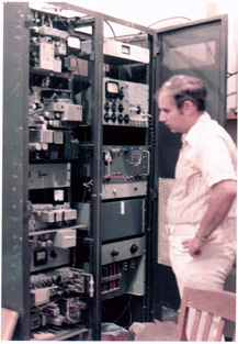
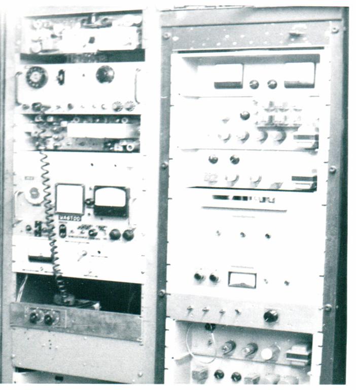
Below is a picture of the WA6TDD repeater circa 1969 taken in my home workshop. The repeater had been brought down for a major re-working. Two weeks later it was back on Mt. Wilson. The two 7’ racks were scrounged from one of the TV stations on Mt. Wilson.
The equipment from top to bottom in the left rack is the original remote control telemetry generator, the ARC-4 10 Watt AM auxiliary transmitter (with the two large meters), a converted G.E. Pre-Progress 420 MHz 1 Watt telemetry link transmitter, the remote controlled modulation level adjustment, the 100 Watt AM Main transmitter with a 4CX250-B final modulated by a pair of 807's and the power supply for the 100 Watt transmitter.
In the right rack starting at the top are the 2-Meter AM receiver that had the 8 kHz Collins Mechanical Filter, the mic pre-amp for the "inside the rack" microphone, the audio processing and logic chassis for the repeater, the wide-band 420 control link receiver, the remote control deck containing a 26 position stepper and the super-sonic tone decoders for the Step, Reset, Raise and Lower functions, and a 24 Volt DC power supply.
Most of this equipment is still stored in racks in my garage.
Burt, K6OQK
The repeater was constantly going through technical changes and never looked the same twice. This picture was taken in 1975 by JA1FQO who made a special trip from Japan to see the repeater. By this time it had become an FM only repeater.
The equipment in the left rack from the top: The Motorola 30-D auxiliary transmitter that was modified for direct FM, the Motorola 140-D main transmitter also modified for direct FM and it's power supply, a panel containing a 5 kHz low-pass audio filter that preceded both transmitters, a G.E. Pre-Prog 420 receiver that was used as the link receiver, the FM Sensicon-A receiver’s metering panel, and the Sensicon-A receiver’s power supply and motorized remote squelch control.
The equipment in the right rack from the top: A CBS FM Volumax that limited the peak deviation to 4.5 kHz without clipping, the audio processing and logic controller, the control link's super-sonic control tone decoder and control logic, the 24 VDC power supply; A strange drum recorder from the telephone company that was modified for voice ID's that could be recorded over the control link, the interface for the drum recorder, and a 247-B touch-tone decoder that was tuned to non-standard touch-tone frequencies to control the system via telephone.
The Repeator in 1975
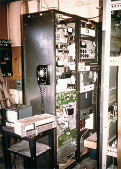
The WR6ABE / WA6TDD repeater as it looked in 1980
At the top of the right rack is the custom FM repeater receiver that was built by Ray Von Neuman K6PUW, Ed Farley W6EF, Bob Thornburg WB6JPI, and Burt Weiner K6OQK. There was nothing that could compare with this receiver’s ability to hear extremely weak signals in such a harsh environment as Mt. Wilson. The two units in the lower left with the green panels are the TVM-1 microwave receiver.
This is the WA6TDD / WR6ABE Repeater circa 1981. Immediately to my back is the modified RCA BTF-1C FM Broadcast Transmitter that made 1200 Watts on 2-Meters. The repeater’s duplexer is at the top left of the picture. In the foreground on the left is KPFK’s microwave and control rack.
The WR6ABE / WA6TDD STL (Shack Transmitter Link) in Woodland Hills circa 1981. In the right rack at the top is the RCA TVM-1 Microwave transmitter control unit. Below that are the 6.8 and 6.2 MHz sound channels modulators, and below that is the Moseley PBR-30 remote control. The control unit in the bottom of the rack was a spare unit. The equipment in the left rack was video equipment that fed the microwave’s video channel in the hopes that someday we’d figure out something fun to do with it.
WA6TDD / WR6ABE Audio Logging and Monitoring
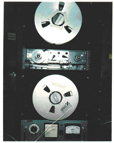
This picture shows the monitoring and audio logging equipment that was in use about 1969. The monitor receiver is a G.E. ER-1A. The two meters at the top were hooked to the receiver, one to monitor modulation and the other to monitor center frequency. The system was regularly calibrated against a Gertsch FM-7. The ER-1A receiver was later modified to bring out the 20-30 Hz sub-audible telemetering signal from the discriminator.
Below the speakers are two Warwick ARN-174 Military audio logger recorders that were used prior to the monster logger. The Warwick recorders used a 7” reel of 2” wide tape that lasted 24 hours each when running continuous. We keyed the motor from a carrier operated relay to save tape. I still have one of the Warwick units and about 15 or so reels of recorded tape from the WA6TDD / WR6ABE repeater.
The 14” Monster Audio Logger
This is a picture of the later version of the Audio Logger for the repeater. The basic unit was a Soundscriber S-124 donated to the project by Marv Collins, W6OQI who was the chief engineer at KFI Radio. It used 2" wide tape on 3" reels. Each 3" reel would normally last 24 hours and 15 minutes. A carrier operated relay was connected in series with the Soundscriber’s motor leads so that it only recorded when the repeater was on the air.
It was decided that a method of recording longer time periods was needed. So we proceeded to go directly towards insanity and use 14” reels of Video Tape. The spindles were from an Ampex 2" Quad videotape machine. Harry Wells, W6YLC machined and fitted the spindles to two washing machine motors and mounted them to 3/16" thick rack panels. Holdback tension on the top, supply reel was accomplished by applying about 1 VDC to the motor. The bottom, take-up reel tension was accomplished by applying about 6 VAC to the motor. There was no rewind or fast forward because we feared for our lives.
With the 14" videotape reels we could record 30-40 days continuous. The problem now became - how did you go back about two or three weeks to find something that someone thought may have happened around a certain time. We couldn't. It took too much time. On more than one occasion I invited people who wanted something from the log tape to come and find it themselves. They usually took one look at the logger and ran away.
If you look at about the 2:00 position on the bottom reel you can see where pieces of paper were slipped between layers of tape. These pieces of paper had dates and times written on them when interesting things took place. Even with that it was still a real headache to go and retrieve something. It finally came down to that if something interesting happened we would grab it out of the logger right away and dub it to a cassette.
A somewhat humorous side story is that in the process of trying to locate 14" reels of tape a call went out on the repeater. Shortly afterwards reels started to mysteriously appear on our front door step. After a couple of months of this there was more tape than we could've ever used. I got on the repeater numerous times thanking whoever was delivering the tape and asked them to please stop. The mysterious deliveries increased. There were times I could not get through the front door in the morning because of the pile of reels. There were no labels on the tapes that might have given a clue as to where they were coming from and they had been bulk erased. Finally the midnight deliveries stopped just as they had started. And yes, I still have the S-124 Soundscriber.
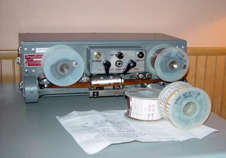
A basic Soundscriber model S-124
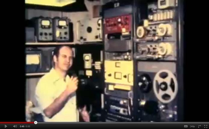
K6OQK Pounding on the repeater - The RCA Method of Repair
Actually, I was installing the first WA6TDD FM receiver, a Motorola Sensicon A that listened on 145.195 MHz.
In the rack to the right is the WA6TDD Voice ID Cart system that was located at our home. It sent audio to Mt. Wilson via the the 420 MHz Control Link in the system’s duplex mode. It worked by sensing silence on the repeater for 5 seconds before triggering itself and was locked out from sending more than one ID in 5 minutes. The repeater had to already be on the air in order for it to trigger. It would not bring it up by itself. The carts were standard NAB carts with the exception that they had a 25 Hz tone at the end of the message to release the system. In the left rack is the original remote control and below that is a second radio controller that was built. Sorry the picture is so bad.
This is the WA6TDD / WR6ABE control system and some of the peripheral audio gear located at our home in Woodland Hills circa 1975 AD. By this time we had gone from the monster logger back to the standard Soundscriber loggers for practical reasons.
For more details see:
https://www.youtube.com/watch?v=Ik6LUs60S9c
And then:
https://www.youtube.com/watch?v=_pjJfz8RHsg
Or, you can go to www.youtube.com and do a search for WA6TDD or K6OQK.
Art and Millie Gentry
By Burt Weiner, K6OQK
From QST Magazine March 2004
I must have arrived on Earth with an inborn interest in radio. It didn’t develop; it was just there from the very beginning. It so happened that my folks were close friends with Sam and Mildred Balter. Sam was a sports announcer on radio and television and quite aware of my interest in radio. One day, when I was about 5 years old, Sam took me to work with him and introduced me to some of the announcers and engineers.
This one event probably did more to turn my interest toward broadcasting than anything else. I went back to the station as often as I could talk someone into taking me. When I was old enough I would take the bus to the station. I went almost every Saturday and Sunday and just “hung around.” I drove people nuts! Some, but not all, of the engineers found it easier to give me something to do than to make me go away. One of the engineers was named Art. I sensed that Art thought I really should be home, or at least somewhere else. When I saw Art coming I’d make it a point to be somewhere else. This was an often-repeated ritual.
When I was in junior high school, I received my ham call, KN6OQK, and found my way to 2 meters. Then one day I heard this “thing.” It just stayed on the air and I could hear people talking to each other. Not only that, from time to time it beeped. I listened for a few days and finally figured out that this “thing” was called a repeater. I discovered the input frequency and climbed aboard. I remember a female voice welcoming me. Her name was Millie, K6JJN.
Millie’s husband, whoever he was, had built the repeater thing. One day I struck up a conversation with Millie’s husband, Art, W6MEP. Art and I got on well together. It never dawned on me, and I’m sure not to Art either, just who either of us really were. At least I never put the two Arts together. I was still going to the station, but just not as often now. The distant relationship with the Art at the station remained.
One day a ham radio buddy told me he was going out to visit Art and Millie and invited me to go along. We arrived about four in the afternoon. Art had just called Millie on the radio to let her know he was leaving work. Who knew what he did for a living? I certainly didn’t! She handed me the microphone and told me to keep Art company. We had a great time. Art was telling me about the “repeater thing” and “how he did it.”
As Art got closer to home I was getting really excited. I was finally going to meet him. I heard the car pull into the driveway. I heard the car door open and close, then foot-steps, then the kitchen door opened, and there he was! Art’s mouth gaped! He just stared - in absolute disbelief. I was trapped in a corner of the kitchen with nowhere to go! All the while Mille was staring strangely at both of us.
Then something happened. He slowly started to smile and slowly walked over to me and gave me a hug, one of the warmest hugs ever. This was the beginning of a very special bond between Millie, Art and myself that would last a lifetime.
On May 10, 1996, Art passed away. Millie joined him on August 5 the same year. I miss them more than words can describe. They changed my life in a way I could never have imagined.
Back to the main page!
Last Up Date 01-01-14!